Design rules
Basic rules
The ORP project aims to develop a user-friendly library of robotics parts. These parts adhere strictly to design guidelines and prioritize simplicity and minimalism. The project considers three different manufacturing methods for designing these parts:
- 3D printing - This is the most popular and easiest solution available today. Simple plastic FDM (Fused Deposition Modeling) parts are generally strong enough for both hobbyist and research robotic projects.
- Laser cutting - Laser cutting allows for the use of materials beyond plastic, such as plywood and metals. The manufacturing process is quicker, enabling higher-scale production.
- CNC machining - CNC machining serves as an alternative to laser cutting. However, it is not recommended to use complex geometries.
Please note that these rules for different part categories are currently a "work in progress" at this early stage of the project. They may be subject to change in the future based on user feedback. If you would like to provide feedback and contribute to the project, please fill out this form.
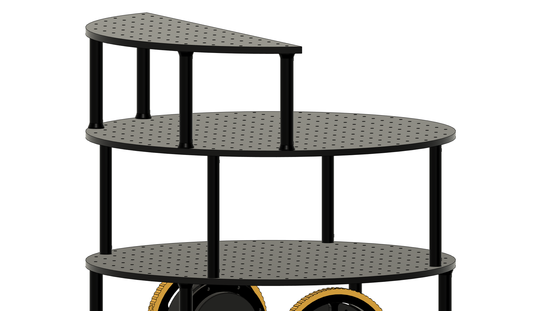
Plates
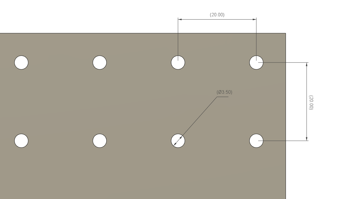
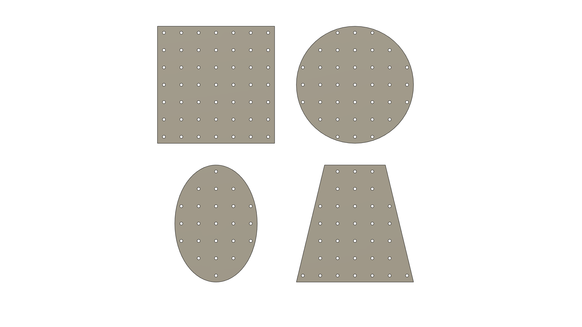
The foundation of each ORP chassis and the entire project is the hole pattern. This pattern is a crucial aspect of the design. For every plate, there is a hole starting from the center, and holes are spread out across the entire plate at 20mm intervals in X and Y. Hole diameter must be exactly 3.5 mm. The plates are categorized as follows:
- Rectangular - These plates can be rectangular, square, or trapezoidal in shape.
- Circular - This category includes plates that are perfect circles.
- Oval - Any oval-shaped plate that is not a circle falls into this category.
- Special - Plates in this category are designed for specific use cases or have specialized cutouts to accommodate specific requirements.
- Weird - This category encompasses plates that do not fit into the aforementioned categories.
It is highly recommended to share the parts in both DXF and 3MF formats. The DXF format is particularly useful for compatibility with laser cutters and CNC machines. Importing the DXF file into a CAD environment also facilitates adjustments and modifications for 3D printing. Additionally, including a 3MF file with each part submission ensures easy printing.
- Thickness - While there are no specific rules regarding plate thickness, it is important to consider the rigidity of the plate. The thickness should be chosen appropriately to ensure the desired strength and stability.
- Material - All plates should be designed in a way that allows for the use of various manufacturing methods and materials. For special use case parts, it is recommended to mention the minimal thickness and the specific material required.
- Hole diameter - All holes on the plate should have a diameter of 3.5mm. This diameter allows for successful use with any manufacturing method and enables the use of popular 1/8 inch milling bits for CNC machining. M3 screws easily fit into these holes, and if necessary, some of the holes can later be drilled to a larger diameter (such as 5mm or more) to accommodate larger screws for mounting purposes.
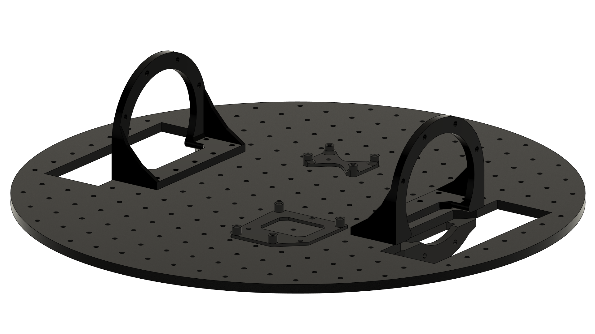
- Wheel cutouts - Most plates will likely include wheel cutouts. While there are no strict rules regarding their design, it is important to include the design file of a plate without cutouts as well.
Holders
All holders in the ORP system are designed to fulfil a basic functionality, serving as interfaces between ORP plates and other parts used in robotics projects. Custom-designed parts can incorporate the ORP hole pattern and be directly attached to the plates, while non-compatible elements will require custom holders. To ensure versatility, it is preferred that holders are designed to fit multiple similar parts. For example, a holder designed for an Arduino Uno should also be compatible with an Arduino Leonardo and similar boards. Similarly, a Nema23 motor holder could feature a hole pattern that accommodates Nema17 motors as well.
Considering manufacturing simplicity, most holders should be designed for 3D printing. However, bent metal holders are also acceptable. The description of each holder should specify its purpose and list the compatible elements it can accommodate.
The following categories are defined for holders within the ORP project:
- Motors - Holders for any type of motor used in a robot, including actuators and servos
- Sensors - Designed for any type of sensor, PCB, module, or circuit used in robotics projects.
- Microcontrollers and SBCs - Intended for microcontrollers and Single Board Computers (SBCs) such as Arduino, Raspberry Pi, Jetson Nano, etc.
- Cameras - Any type of camera.
- Batteries - Including power banks, LiPo batteries, gel batteries any others.
- Special - Specialized holders for unpopular or custom parts.
- Other - If it doesn't fit above it fits here.
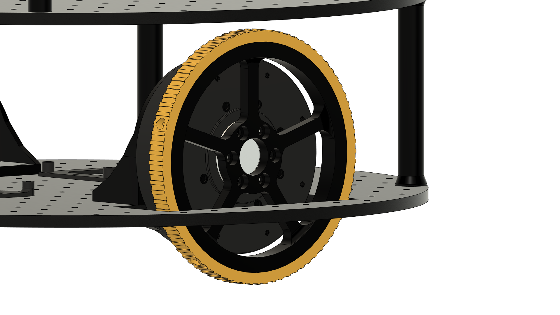
Wheels
Wheels within the ORP system are considered the least constrained parts, allowing for a wide range of options for robot actuation. A wheel can be any component that enables the robot's movement. The ORP project distinguishes the following types of wheels:
- Smooth - These wheels have a smooth surface without any specific tread pattern. They are suitable for applications where traction is not a primary concern.
- Normal - Wheels in this category feature a standard tread design that provides increased traction. They are versatile and can be used in various robotic applications.
- Terrain - These wheels are specifically designed for outdoor use, providing enhanced performance on uneven or rough surfaces.
- Spikes - Wheels in this category are equipped with spikes or specialized tread patterns for extra grip on challenging terrains or for use on icy surfaces.
- Special - This category includes any wheel with a unique design or intended for specific use cases not mentioned in the above categories.
Connection rods
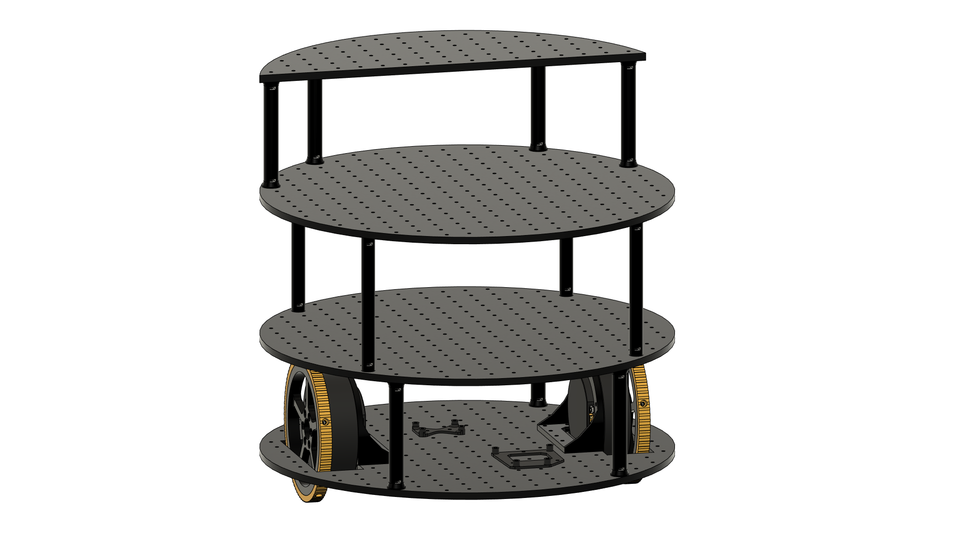
Connection rods are utilized to stack plates on top of each other, expanding the available mounting space and facilitating the creation of multi-floor robots. The ORP project defines the following categories for connection rods:
- One hole - This type of connection rod attaches to a single hole on the plate. It provides a basic connection point for stacking plates.
- Multi holes - Connection rods in this category attach to multiple holes on the plates, offering enhanced stability and support when stacking multiple plates together.
- Special - This category encompasses non-standard connection rods that have unique designs or features tailored for specific use cases.
Submission rules
Each parts should be submitted individually. The part name should clearly describe the purpose of the part as well as the size information in mm. Preferably multiple files should be uploaded with each part (DXF, 3MF, STEP). Any additional information should be provided in the description.
Only one image can be uploaded with each part. Please make sure that the part is nicely visible, the contrast is high and it is easy to distinguish the shape and use case of the part just based on the image.
All parts of the ORP system are shared under MIT license!